Reviewed by: Alfonso Cordova, Sales Automation and Michael Ishlove, Technical Manager
Last reviewed: July 2026
You commission a variable frequency drive. The motor runs for a while. Then the bearings start making noise. Temperatures creep up. Eventually, you're looking at an unplanned shutdown and a winding failure that nobody saw coming or rather, one that had been telegraphing itself for months.
This is what a motor-drive mismatch looks like in practice. And it's more common than most engineers want to admit.
A significant portion of Canada's installed industrial motor base comprises standard-frame motors never designed for VFD compatibility. When those motors get paired with VFDs, whether due to a system upgrade, a cost-saving decision or an inherited installation, the results range from reduced service life to catastrophic failure.
This guide is for the engineer standing at that junction, and as we know at VJ Pamensky (WEG Canada), it’s a crossroads more engineers are facing than ever. Not the one specifying a greenfield system from scratch, but the one asked to evaluate what's already running, decide whether the risk is manageable and choose the right path forward: protect, retrofit or replace.
VFD compatibility is a structural specification, and the gap between a VFD-rated motor and a standard motor matters the moment you connect a drive.
NEMA MG 1 Part 31, the governing standard for inverter-duty motors and installations, requires insulation systems capable of withstanding peak voltages of up to 3.1 times rated line-to-line voltage for low-voltage motors (?600 V). That's up to 1,860 V on a standard 600 V system. WEG inverter-duty motors rated up to 1,000 V are built to withstand 2,400 V, providing meaningful headroom above the standard minimum. NEMA MG 1 Part 30, which covers general-purpose motors used with VFDs, limits safe operation to a peak of 1,000 V at the motor terminals with rise times at or above 0.1 ?s. Exceed those parameters and you're degrading insulation every operating cycle.
Beyond winding insulation, VFD-rated electric motors incorporate:
A standard motor has none of these provisions. That's not a motor design flaw, it's a specification boundary. Standard electric motors are designed for sinusoidal power at fixed frequency. Put a PWM drive in front of one, and you've changed the operating conditions entirely.
Understanding the VFD failure mechanisms helps you diagnose what's already happening and anticipate what comes next.
A VFD doesn't output smooth AC. It switches IGBT transistors at high frequency to synthesize a voltage waveform, producing a series of rapid-rise pulses rather than a true sine wave. When those pulses travel down the cable to the motor, impedance mismatch between the cable and motor terminals causes the voltage wave to reflect back on itself.
The result: peak voltages at motor terminals that can reach 1.5 to 2 times the DC bus voltage. On a standard 600 V system, you can see transient peaks in excess of 1,600 V, well beyond what NEMA Part 30 general-purpose insulation is rated to handle. Cable length amplifies the effect. Longer runs mean more voltage overshoot and longer rise times, accelerating the problem.
This is the failure mode engineers most frequently misdiagnose as a lubrication or alignment problem.
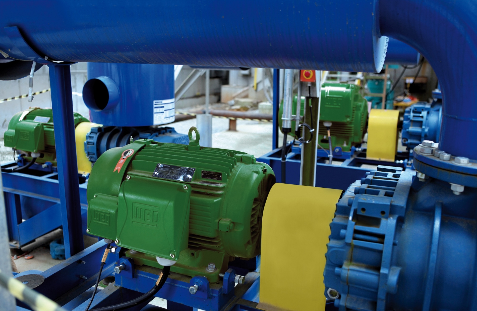
VFDs generate common-mode voltage, a voltage that appears equally on all three output phases relative to ground. This creates a capacitively coupled voltage on the motor shaft. In a standard motor with conductive bearings, the shaft discharges through the bearing to the frame. Each discharge event is essentially a small arc: electrical discharge machining (EDM) that pits and flutes the bearing raceway over time.
Bearings account for roughly 50-60% of motor failures in VFD-driven applications. The signature is unmistakable on inspection: frosted or pitted bearing raceways, often showing the distinctive washboard pattern of fluting. By the time vibration analysis picks it up audibly, significant damage has already occurred.
In electric motors above 100 HP/75 kW, high-frequency circulating currents also develop, traveling from shaft to frame through one bearing and back through the other, compounding the damage rate.
Standard motors use a shaft-mounted fan for cooling. At reduced speeds, precisely where variable-speed operation is most useful, that fan moves proportionally less air. The result is inadequate heat dissipation at the very operating point where the motor is working hardest.
Winding insulation degrades exponentially with heat. The Arrhenius rule of thumb holds that every 10°C increase in operating temperature above rated design halves insulation life. A standard motor running hot under VFD control at 30 Hz isn't just uncomfortable, it's accelerating toward a winding failure that would have taken years under direct-on-line operation.
Recognizing the early symptoms of VFD incompatibility is how you catch a maintenance event before it becomes a production outage.
Overheating: Motor frame temperatures are consistently higher than expected for the load. Infrared thermography showing hot end-windings or uneven thermal distribution. These patterns suggest inadequate cooling at reduced speed or insulation already breaking down.
Unusual bearing noise: A high-frequency hiss or grinding that doesn't respond to lubrication. This is the acoustic signature of EDM fluting in progress. If you're replacing bearings more frequently than the manufacturer's motor design life would suggest, EDM is the likely culprit.
Nuisance trips and ground faults: Overcurrent trips without a clear load cause or ground fault indications that appear intermittent. Degraded winding insulation produces leakage current that triggers protective devices. These trips are the drive telling you something is wrong with the motor, not itself.
Premature winding failures: Rewinds happening well short of expected service intervals. Standard motor windings account for roughly 16% of motor failures overall, but that figure rises significantly in VFD-driven applications where insulation was never rated for PWM stress.
Vibration increases: Trending vibration data showing progressive growth in the bearing frequency bands. Combine with shaft voltage measurements to confirm EDM as the root cause before condemning the bearing outright.
Before recommending motor replacement, it's worth evaluating whether protection measures can extend the useful life of the existing motor. The answer depends on what failure modes are active and how far degradation has progressed.
Installed between the drive and motor, dV/dt filters slow the rate of voltage rise, reducing the peak voltage stress at motor terminals. For applications where the primary concern is insulation stress from reflected wave voltage, a well-selected dV/dt filter can bring terminal voltages within NEMA Part 30 limits and meaningfully extend winding life in a standard motor.
When it's viable: Motors with no existing insulation damage, cable runs long enough that reflected wave effect is the dominant stress mechanism, applications where the motor is relatively new and insulation resistance tests (megger readings) confirm baseline integrity.
Limitation: dV/dt filters reduce shaft currents but do not eliminate bearing EDM. For electric motors already showing bearing-frequency vibration signatures, a filter alone won't solve the problem.
AEGIS-type conductive microfiber shaft grounding rings provide a low-impedance path from shaft to frame, diverting shaft discharge currents away from the bearings. This is the most targeted solution for EDM-related bearing failure.
When it's viable: Motors where vibration analysis has confirmed bearing current as the damage mechanism, retrofits where bearing replacement is already planned and situations where the motor is otherwise in good condition.
Limitation: Grounding rings address capacitive EDM current effectively. In large motors (>100 HP/75 kW), high-frequency circulating currents may also require insulated bearings on the non-drive end to break the circulating current path.
Switching frequency, carrier frequency selection and acceleration/deceleration ramp settings all influence the severity of motor stress. Reducing the carrier frequency lowers common-mode voltage generation but increases audible noise. Adjusting ramp times reduces thermal shock during starts. These are low-cost interventions worth attempting before committing to hardware changes.
When it's viable: Early-stage diagnosis where insulation and bearing integrity are still confirmed good. Parameter tuning is a complement to protection hardware, not a replacement for it.
Shielded cable with the shield grounded at both ends reduces common-mode EMI and helps limit ground current paths. Keeping cable runs as short as practically possible reduces reflected wave amplitude. These are installation-side measures that should be standard practice for any VFD installation, regardless of motor rating.
Protection measures buy time and reduce ongoing stress. They don't reverse existing damage. There are scenarios where the engineering decision to replace, rather than protect, is the correct one and deferring that decision carries real cost.
Replace when:
Use this structured decision path when evaluating a non-VFD-rated motor in an existing drive application:
Step 1: Assess motor condition
Step 2: Evaluate operating hours and age
Step 3: Classify application criticality
Step 4: Calculate total cost of ownership
Step 5: Decide and document
If the motor has good insulation and no bearing damage in a non-critical application, protection is the right call: install a dV/dt filter and a shaft grounding ring. If minor bearing wear is present but insulation is intact, go ahead with protection measures and plan a bearing swap with a grounding ring at the next scheduled PM.
If insulation has degraded or any bearing EDM is confirmed, replace it with an inverter-duty motor. Don't invest in protection hardware for a motor that's already compromised. The same applies to any rewound motor, regardless of how recently the rewind was completed.
For critical applications, replace it with an inverter-duty motor regardless of current condition. The downtime cost of an unplanned failure in a critical process will almost always exceed the cost of proactive replacement. Apply the same logic to any motor over 10 years old that has been running in VFD service. Protection measures at that stage are diminishing returns.
Motor-drive mismatch is an engineering problem with an engineering solution, but only if you approach it systematically. The failure modes are predictable. The diagnostic methods exist. The decision criteria are clear.
Running a non-VFD-rated motor on a variable frequency drive isn't automatically a catastrophe. But it is a risk that compounds silently and the cost of ignoring the signals, overheating, bearing noise, nuisance trips, almost always exceeds the cost of acting on them early.
For many applications, the right answer is a properly specified WEG inverter-duty motor: one built to NEMA MG 1 Part 31, with insulation rated to withstand the stress of PWM switching, insulated bearings to interrupt EDM current paths and forced-air cooling that maintains thermal balance across the full speed range. All WEG inverter-duty motors are CSA approved, with certification marked directly on the motor nameplate. Verify CSA approval on the nameplate prior to installation and commissioning. When the motor is right for the drive, the protection measures become insurance rather than a lifeline.
Start with the diagnostic framework above. Know what you're working with before you decide what to do about it.
Ready to evaluate your motor-drive compatibility?Contact V.J. Pamensky today for application-specific guidance on WEG inverter-duty electric motors, protection solutions and VFD system integration across Canada.
Reviewed by: Alfonso Cordova, Sales Automation and Michael Ishlove, Technical Manager
Last reviewed: July 2026
A standard motor can be used with a VFD in limited conditions, specifically, where peak voltages at motor terminals stay below 1,000 V and rise times remain at or above 2 microseconds, per NEMA MG 1 Part 30. In practice, this restricts cable runs, drive switching frequency and speed range. For most industrial applications with variable speed requirements, a VFD-rated (inverter-duty) motor is the safer and more cost-effective long-term choice.
It indicates the motor meets NEMA MG 1 Part 31 requirements: insulation capable of withstanding peak voltages of at least 1,600 V (with many motors rated to 2,000-2,200 V), a speed range of 1,000:1 for variable torque or 20:1 for constant torque and construction features designed for PWM drive operation. Check the nameplate for explicit NEMA MG 1 Part 31 designation, "inverter-ready" or "inverter-friendly" are not equivalent.
Vibration analysis targeting bearing defect frequencies is the most reliable non-destructive method. Shaft-to-ground voltage measurements above 500 mV peak suggest active EDM current. On inspection, EDM-damaged bearings show frosted or pitted raceways and, in advanced cases, characteristic fluting, parallel grooves running circumferentially around the raceway. If you're replacing bearings more frequently than expected without a load or lubrication explanation, EDM is the likely cause.
The primary options are dV/dt output filters (installed between drive and motor to reduce voltage rise rate and limit peak voltages), shaft grounding rings (to divert bearing discharge currents to frame), shielded cable with dual-end grounding and drive parameter tuning to reduce carrier frequency and optimize ramp settings. These measures extend motor life but do not eliminate the fundamental compatibility gap, they are most effective on electric motors with no existing damage.
Replacement is the better option when insulation resistance tests show degraded readings (below 1 M? per 1,000 V operating voltage), when the motor has been previously rewound, when the application is critical enough that an unplanned failure would be costly or when the motor is operating under constant torque at low speed where standard cooling cannot maintain thermal balance. The total cost of ownership, protection hardware plus ongoing maintenance and risk of failure, usually favours replacement within two to three years in these scenarios.
Yes, significantly. Longer cable runs between a VFD and motor increase the reflected wave effect, the impedance mismatch that causes voltage to overshoot at motor terminals. The longer the cable, the higher the potential peak voltage and the more severe the insulation stress. NEMA guidelines suggest consulting the motor manufacturer when peak voltages are expected to exceed 1,000 V or rise times fall below 2 microseconds. dV/dt filters are particularly effective at mitigating long-cable voltage overshoot.
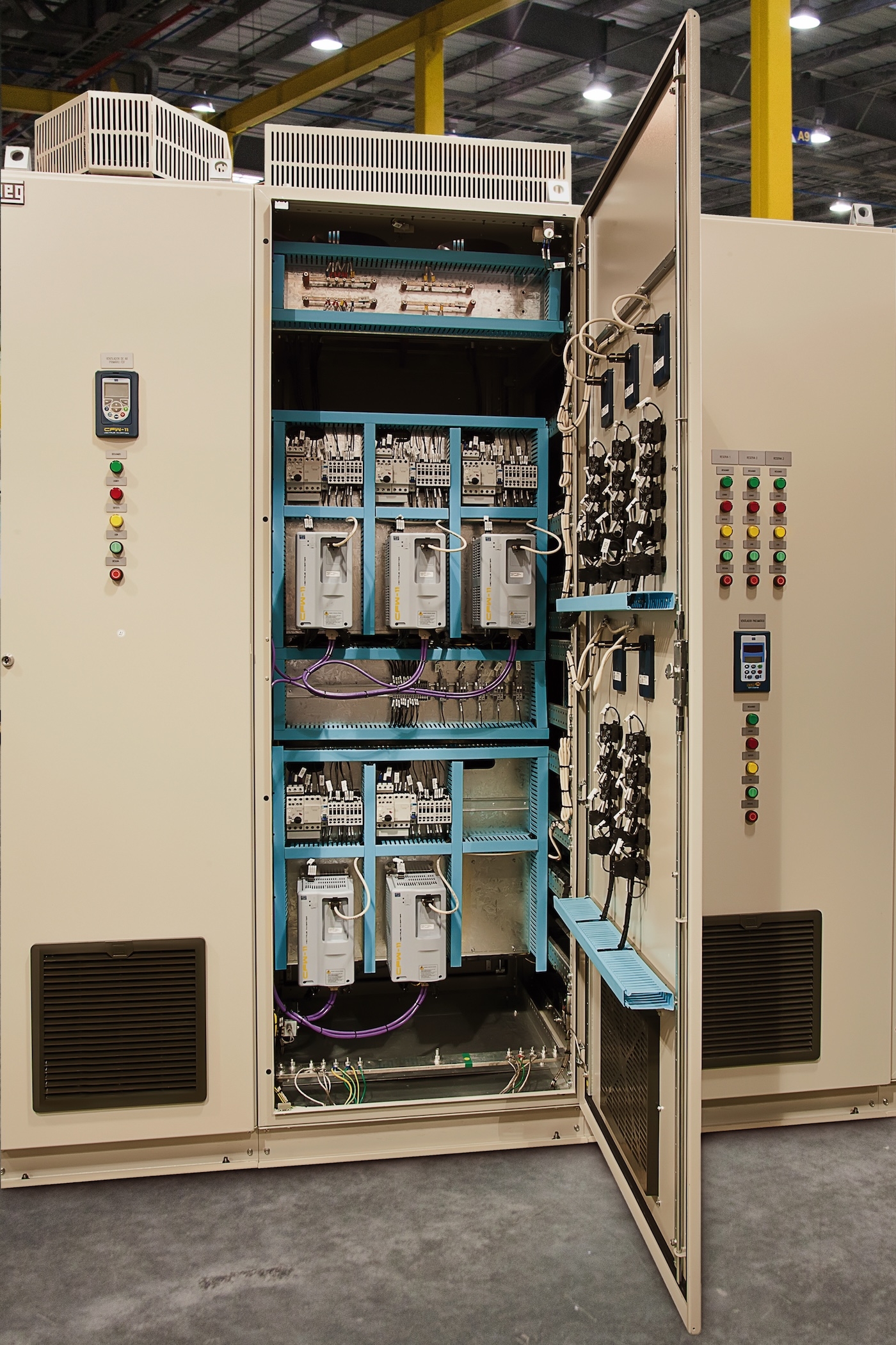
Look for explicit NEMA MG 1 Part 31 compliance, insulation class F or H with a Class B temperature rise (providing a thermal margin buffer), 1,600 V minimum insulation rating (2,000-2,200 V preferred), insulated bearings on the non-drive end for motors above 100 HP and a shaft grounding provision. WEG's W22 and W50 inverter-duty frames meet these requirements and are designed for direct compatibility with WEG CFW-series VFDs in Canadian industrial applications.