Reviewed by: Michael Ishlove, Technical Manager
Last reviewed: June 2026
For OEMs designing or specifying drive systems, pairing an electric motor with a variable frequency drive is not simply a horsepower-matching exercise. The motor and drive need to work together electrically, thermally and mechanically.
Many VFD-related motor failures are not caused by defective equipment. They result from compatibility issues between the drive, motor, cable installation and operating environment.
When those compatibility factors are ignored, the consequences can include overheating, bearing damage, insulation breakdown, winding failure and unplanned downtime.
This article explains the most common VFD-related industrial motor performance risks, why they occur and how OEMs and industrial teams can reduce long-term reliability problems through proper motor-drive specification.
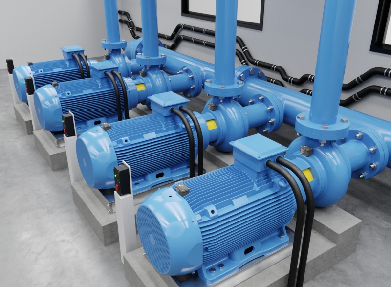
Motor-drive compatibility means the motor can handle the electrical, thermal and mechanical conditions created by VFD operation.
This includes more than matching voltage, horsepower and speed. The motor must be suitable for the drive’s output waveform, cable length, switching frequency, thermal load, bearing protection requirements and operating speed range.
For OEMs, this matters at the motor design stage. Specifying a motor and drive as a matched system, rather than sourcing them independently and hoping they work together, helps reduce failure risk, warranty exposure and long-term service issues.
The most significant electrical threat VFDs pose to motors is the reflected wave phenomenon. When the VFD's fast-switching transistors (IGBTs) send voltage pulses down the motor cable, those pulses travel as waves. If the cable's impedance doesn't match the motor's impedance, which it almost never does perfectly, the wave reflects back toward the drive. The original pulse and the reflected pulse then combine, creating voltage spikes that can reach two to three times the drive's DC bus voltage.
On a 600V system, that means transient spikes potentially exceeding 1,600V at the motor terminals.
Standard motor insulation systems are rated for the nominal line voltage, not for repeated high-frequency transients at multiples of that voltage. Every spike degrades the insulation incrementally. It's not a single catastrophic event, but rather a cumulative stress that shortens winding life over months or years of operation.
Three factors amplify reflected wave severity:
This is why cable management isn't an afterthought in VFD installations, it's a core compatibility variable.
Thermal management is one of the most underappreciated compatibility factors. Standard induction motors are designed to run at or near their rated speed, where the shaft-mounted cooling fan moves enough air to dissipate heat effectively. Run that same motor at 20% speed on a VFD and the fan moves a fraction of its rated airflow, a dramatic reduction that leaves the motor thermally starved.
At low speeds, the motor may be doing real work, carrying significant torque, while generating almost no cooling. The result is localized overheating in the windings, accelerated insulation breakdown and shortened motor life.
VFD-rated motors address this with separately powered cooling fans (forced ventilation) that maintain airflow regardless of shaft speed. For OEMs specifying motors for variable-speed duty across a wide speed range, this distinction is critical.
Bearing currents are one of the more insidious failure modes in VFD-driven systems and one of the least understood until bearings start failing prematurely.
VFDs create common-mode voltage: a high-frequency voltage that appears equally on all three output phases relative to ground. This common-mode voltage induces a voltage on the motor shaft. When that shaft voltage exceeds the dielectric strength of the bearing lubricant film, current discharges through the bearing, from the shaft, through the rolling elements, to the outer race and into the motor frame.
Each discharge event is tiny. But at VFD switching frequencies, these events happen thousands of times per second. The cumulative effect is electrical discharge machining (EDM) of the bearing surfaces, microscopic pitting called fluting that creates a washboard pattern on the bearing races. The bearing becomes noisy, then rough, then fails.
This failure mode is particularly common in motors above 100 hp, where shaft voltages are higher and in systems with long cable runs that increase common-mode current.
Beyond thermal stress and bearing damage, the repeated voltage transients from VFD operation attack the turn-to-turn insulation within the motor windings. The first few turns of the winding, closest to the motor terminals, absorb a disproportionate share of the voltage stress. Over time, partial discharge activity erodes the insulation at these points, eventually causing turn-to-turn shorts and winding failure.
This failure pattern is distinct from standard motor failures and often catches maintenance teams off guard, because the motor may have been running for years before the accumulated damage reaches a critical threshold.
Older motors, those designed and manufactured before VFDs became standard, were built to a different set of assumptions. Their insulation systems used materials rated for sinusoidal voltage stress, not high-frequency PWM transients. Their bearing designs didn't account for shaft currents. Their thermal management assumed constant-speed operation.
Retrofitting a VFD onto an existing motor without assessing its suitability is one of the most common sources of premature motor failure in Canadian industrial facilities. The motor may run fine initially. The degradation is gradual and invisible until something fails.
Key vulnerabilities in older motors include:
The older the motor, the more carefully its suitability for VFD operation should be evaluated before the drive is installed.
Many VFD failures appear after retrofit projects where an existing motor is connected to a drive without reviewing insulation condition, bearing design, cooling requirements or cable installation.
In these situations, the motor may appear to operate normally at first while insulation degradation, overheating or shaft current damage develops gradually over time. Retrofit applications should include insulation testing, cable review and confirmation that the motor is suitable for inverter-duty operation before the drive is installed.
Motor-drive mismatch does not always announce itself immediately. Many compatibility problems develop gradually before a catastrophic failure occurs. Early warning signs often appear through maintenance trends, nuisance faults or unexplained motor behaviour.
OEMs and maintenance teams should treat the following signals as red flags:
Electrical and thermal indicators:
Mechanical and acoustic indicators:
Operational indicators:
Any one of these symptoms warrants investigation. A pattern of two or more is a strong signal that the motor-drive pairing needs to be reassessed, not just the failed component replaced.
The good news: most motor-drive mismatch risks are addressable with the right protection strategy. None of these solutions are complicated. They do, however, need to be planned in advance, not bolted on after the first failure.
Shaft grounding rings are the primary defence against bearing currents. A ring of conductive microfibers contacts the motor shaft and provides a low-impedance path to ground, diverting shaft current away from the bearings entirely. The shaft grounding ring bypasses the bearing, so the discharge that would otherwise pit the bearing race has somewhere else to go.
For motors above 100 hp, where shaft voltages and common-mode currents are highest, shaft grounding should be considered standard practice, not optional. On larger motors, insulated bearings on the non-drive end are often added as a second layer of protection.
Three filter types address reflected wave and voltage spike risks, matched to cable length:
Filter selection should always account for motor size, cable type and the VFD's switching frequency. A filter matched to the wrong parameters can introduce its own problems.
VFD-rated cables, shielded, with low capacitance between conductors and the shield, reduce common-mode current and electromagnetic interference. Shielded cable also provides a dedicated return path for high-frequency currents, which reduces the current available to flow through motor bearings.
Keep cable runs as short as practically possible. Route motor cables separately from control and signal wiring to prevent interference. Never route VFD output cables in the same conduit as input power cables.
Installation quality matters as much as component selection because VFD-related motor problems often come from how the system is grounded, wired and commissioned. Key practices include:

There's a point at which protecting an incompatible motor becomes more expensive than replacing it. That point arrives faster than most operations anticipate.
The case for replacement is strong when:
VFD-rated motors, built to NEMA MG1 Part 31 or equivalent standards, are engineered for exactly this environment. Their insulation systems are designed to withstand peak voltages of 1,600V at rise times of 0.1 microseconds. Their cooling systems maintain thermal performance across the full speed range. Their bearing designs accommodate the electrical environment created by modern drives.
For OEMs, specifying an inverter-duty motor from the outset eliminates the need for most retrofit protection measures and removes compatibility uncertainty from the equation entirely. The upfront cost difference is almost always smaller than the cost of one unplanned motor failure, let alone the downstream impact on production schedules and end-user confidence in the equipment.
The right motor-drive combination, specified together and installed correctly, doesn't just last longer. It performs better from day one.
Reliable VFD operation depends on treating the motor, drive, cable and installation environment as one integrated system. When compatibility issues are ignored, the result is usually premature motor failure, unstable operation or increased maintenance cost.
For OEMs and industrial facilities, many long-term reliability problems begin during specification, retrofit planning or commissioning rather than during normal operation itself.
VJ Pamensky (WEG Canada) supports OEMs and industrial facilities across Canada with inverter-duty motor selection, motor-drive compatibility guidance and application support for demanding industrial environments.
Reviewed by: Michael Ishlove, Technical Manager
Last reviewed: June 2026
Motor-drive compatibility refers to how well an electric motor can handle the electrical, thermal and mechanical demands of VFD operation. For OEMs, it matters because an incompatible pairing introduces failure modes, from insulation breakdown to bearing damage, that show up in the field and affect both machine reliability and end-user confidence.
Voltage spikes are caused by the reflected wave phenomenon. VFDs send fast-switching PWM pulses down the motor cable. When these pulses encounter an impedance mismatch at the motor terminals, they reflect back toward the drive and combine with incoming pulses, producing peak voltages that can reach two to three times the nominal bus voltage.
VFDs induce common-mode voltage that builds up on the motor shaft. When this shaft voltage discharges through the bearings, it causes electrical discharge machining (EDM), microscopic pitting of the bearing race surfaces. Over time, this creates a fluted, washboard pattern that causes vibration, noise and eventual bearing failure.
Not without a careful assessment. Older motors were designed for sinusoidal voltage and may lack the insulation rating, thermal management and bearing protection needed for VFD operation. Retrofitting a VFD onto an older motor without evaluating its suitability is one of the leading causes of premature motor failure.
An inverter-duty motor is specifically designed for VFD operation. It meets NEMA MG1 Part 31 requirements, including insulation rated to withstand 1,600V peak transients, inverter-grade magnet wire with higher partial discharge resistance and often a separately powered cooling fan to maintain airflow at low shaft speeds.
The primary options are shaft grounding rings (to divert bearing currents), output filters (load reactors, dV/dt filters or sine wave filters depending on cable length), VFD-rated shielded cable and proper installation, including correct motor grounding and commissioning parameter settings.
Replacement makes more sense when the existing motor has already sustained insulation or bearing damage, when the motor predates inverter-grade insulation standards, when protection costs approach a significant fraction of a new motor's price or when the application involves constant-torque low-speed operation that a standard motor's cooling system can't support.
Longer cables increase the impedance mismatch between the drive and motor, amplifying reflected wave voltage spikes. General guidance: output load reactors for runs up to ~90m, dV/dt filters for 90–300m and sine wave filters for runs beyond 300m. Cable type and shielding also affect the severity of reflected wave and common-mode current issues.